Car wiring diagrams - to know the place of each wire! How to read car electrical circuits? How to read electrical circuit diagrams correctly
Today, the car has long ceased to be a luxury in the family. Today, a personal vehicle has become an integral part of the working day of any business person. For some, this is an indispensable assistant who makes money, for others, another family member who requires constant cash contributions. It’s good when the car is new and trouble-free. There is no need to repair it, headache about replacing filters, oil, wheel alignment, etc. Unfortunately, not many of us are ready to go straight away and buy a new car from the passenger compartment. So you have to face various problems of its restoration and repair. It’s good when there are funds for repairing it by professional car mechanics (although if they were there would be a new car), but when they aren’t available, we, rolling up our sleeves, begin to understand our own car using our own forces and the strength of friends and acquaintances . One of the voluminous topics that requires a detailed explanation is the electrical circuit of the car. Indeed, whether you are the owner of an old "Lada" or a brand new Mercedes, sooner or later you have to deal with replacing fuses, repairing power wiring or updating burned out lamps. Whatever you say, there are quite a lot of electrical circuitry in the car and it doesn’t matter whether it’s old or new, domestic or a foreign car. Of course, it is impossible to cover the entire automotive industry, describing the electrical circuit of the car in one article, so we decided to talk about the operation of the electrical part of the domestic car, as well as talk about the electronics of imported foreign cars. The models will be described not new, for ease of understanding. We will pay special attention to individual electric sensors and components, as well as consider their operation and performance checks, so that a car enthusiast who was unexpectedly met by a road trouble could be ready to solve and eliminate it. To do this, each motorist should have at least the cheapest Chinese tester in the arsenal of the road repair tool, which can check the circuit for a short circuit, the resistance of the sensor contacts and the current voltage.
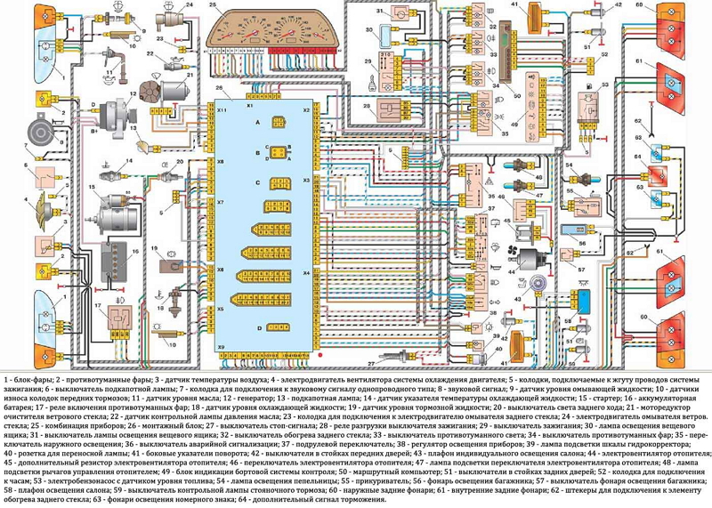
The electric circuit of the car VAZ-2108
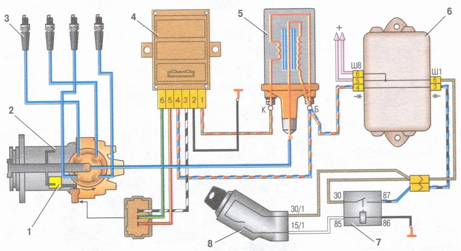
The figure shows the electrical circuit of the VAZ-2108. At first glance, it may seem that the electrical circuit is complex and confusing, in fact it is not. In addition, in this car model, the electrical circuit is considered one of the simplest and most understandable. To understand the operation of the electric part of a domestic car, we will go through the numbering and purpose of the circuit elements. All electrical connections of the circuit for clarity are indicated by conductors of various colors. If the wires go in the harness (and in the car all the wiring goes in harnesses), they are indicated by gray lines with a diagonal strip. This statement applies only to this scheme. The electrical circuit of a car of another model needs to watch its color code for conductors.

1. Block headlight - contains 3 lamps: a passing / driving lamp with two filaments, a marker lamp, and a direction indicator lamp. Only the controlling positive voltage comes here. The mass is taken directly from the car body. If there are problems with the light (blinks, lights dimly or constantly burns out the bulbs, then check the mass first).
2. Electric permanent motors for headlight cleaners (not available on all models, mainly in the export version).
3. Limit switch for the engine compartment light, which lights up when it is opened.
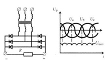
4. Sound horn (sound signal). When it fails, it is necessary to check the relay that controls it, as well as the corresponding fuse.
5. A constant voltage electric motor, on the pulley of which a radiator cooling fan is put on. When the coolant temperature reaches a critical point, the sensor for turning on the electric motor is activated, which closes the 86th relay contact to ground. The relay connects 87 and 30 contacts, the fan starts to work. As soon as the temperature drops, the sensor opens the control contacts, and the fan stops its operation. Positive voltage from the generator is supplied to the relay from the contact group of the ignition switch.
6. A membrane-type temperature sensor that controls the operation of the cooling fan.
7. A three-phase generator that generates a positive voltage of 13.8-15 volts depending on its speed. For rectification inside it, a Larionov circuit is assembled from diodes.
8. The electromagnetic valve that controls the inclusion of the headlight washer system.
9. The electromagnetic valve that controls the inclusion of the rear window washer.
10. An electromagnetic valve that controls the inclusion of a windshield washer.
11. Spark plugs (one for each cylinder). An important element in the ignition of a mixture. The dynamic characteristics of the car, as well as fuel consumption, depend on their condition.
12. The ignition interrupter-distributor that controls the occurrence of current pulses and the appearance of sparks on the spark plugs at a certain point in time (relevant for carburetor engines).
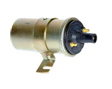
13. The ignition coil, in which the voltage of the on-board network is converted to high-voltage discharges, necessary for sparking on the spark plugs.
14. The end switch of the engine compartment lamp.
15. A sensor that displays the temperature of the coolant.
16. Starter - a permanent engine with a rotor that spins the engine flywheel until a spark forms on the spark plugs. It is necessary in order to start the car.
17. Battery - together with the generator form the main supply element of the vehicle electrical system.
18. Barrels with electronic circuit breaker - float. The sensor indicates the absence or low level of coolant in the vehicle system.
19. Switch - provides control pulses to the ignition coil, which are amplified by the ignition coil and distributed by a breaker to each candle.


20. The sensor of the upper point of the piston of the first cylinder (in injection engines of foreign cars it is a magnetic tooth on the flywheel, or the absence of a tooth).
21. Diagnostic connector for connecting specialized equipment.
22. The solenoid valve control module in the carburetor.
23. Relay through which voltage is supplied from the ignition switch to the starter at the time of the car factory.
24. The trailer, turning off the carburetor.
25. Solenoid valve in the carburetor.
26. Sensor, indicating low oil pressure. The lamp on the dashboard indicates that it is urgent to add engine oil.
27. An electric motor that turns on when washing the windows and forcing the washing liquid.
28. Electric motor stove.
29. Specialized resistance that changes the current of the electric motor of the stove, and, accordingly, the speed of blowing.
30. Stove fan speed switch. It is displayed on the front control panel in the passenger compartment.
31. An electric motor that controls the wipers that clean the windshield.
32. The cigarette lighter, displayed in the cabin.
33. A lamp illuminating the control levers of the stove and heater.
34. A separate outlet for connecting a remote 12 volt lamp.
35. Hood lighting.
36. A lamp that is integrated in the glove compartment and lights up when it is opened.
37. Mounting connection block with switching terminals and fuses.
38. Lighting switch for electrical appliances.
39. Limit switch of a lamp of a lay brake. Usually embedded in its mechanism.
40. Brake light switch (brake light).
41. The steering column multifunction switch for turns, headlight washer and low and high beam switch.
42. Button - head light switch.
43. Button - breaker, activating an emergency stop.
44. Rear fog lamp switch.
45. Fuse for the rear fog lamp circuit.
46. \u200b\u200bButton - rear window heating switch.
47. Side lamps of direction indicators. They are paralleled with front and rear lamps.
48. Lamp for interior lighting of a car.
49. A connector connected in parallel with the interior lamp for additional individual interior lighting.
50. The switch for lighting the side pillars in the passenger compartment.
51. Car ignition relay. Quite often it fails. Check first if the car has stopped showing signs of life and will not start.
52. Contact group ignition.
53. The dashboard, which displays the main devices and warning lights.
54. The limit switch of the lamp signaling the shutter in the carburetor (suction).
55. Taillights containing 5 lamps. The mass is connected similarly to the front lights to the car body.
56. A float-type sensor indicating the fuel level in the gas tank.
57. The electric motor of the rear window wiper.
58. License plate lamps connected in parallel.
This or any other similar electrical circuit of the car can be found in the service manual for the repair and maintenance of a specific model, or on the Internet. Here we examined the assembly generalized scheme. There are also electrical circuits of the car of individual nodes, which in more detail reveal the essence of the work of car electronics. For imported models, basically all schemes are indicated in blocks, or by a node drawing.
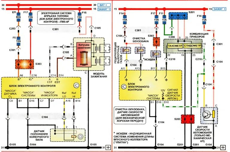
The main sensors of the engine management system and methods for checking them
Below we look at the main engine control sensors in Daewoo vehicles. Such equipment is installed on many cars, so this section will be relevant for most novice motorists.
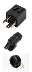
Coolant temperature sensor

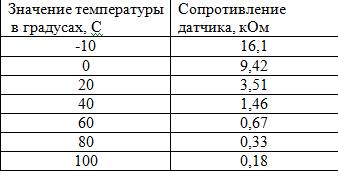
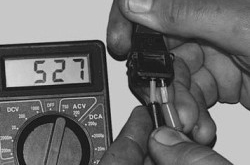
This temperature sensor is a thermistor that changes its resistance depending on temperature. Dependence of change is inversely proportional. The higher the temperature, the lower its resistance. It is checked by the method of measuring resistance with an ordinary electronic tester. The temperature resistance values \u200b\u200bare shown in the table.
If the indicators deviate from the indicated values \u200b\u200bin the table, the sensor will lie. In this case, it is worth replacing.
Air temperature sensor

The air temperature sensor is glued into the air corrugation coming from the air filter to the throttle assembly. According to this sensor, the car computer corrects the composition of the fuel mixture (air / fuel ratio). If it stops working, the computer will go offline. The consumption of gasoline is increasing. In its operation, this sensor is similar to a coolant temperature sensor. At the working sensor, the resistance should correspond to the indicated values \u200b\u200bfrom the table below.

Engine crankshaft position sensor (DPKV)
It is installed in the immediate vicinity and crankshaft. Reacts to the mark of the crankshaft gear. Its task is to make it clear to the computer the position of the piston system. It synchronizes the electronic control of engine parts with ECU data. Very important sensor. Without its adjustment or when it breaks down, the car may stop starting. 3-pin sensor. On its conclusions 1 and 2, the resistance value should be no more than 500 - 600 Ohms.
Throttle position sensor
Often, because of it (or because of the throttle itself), idle speed begins to float, or they become too high or too low. There are 2 types of such sensors: contact and non-contact. Contact sensors are an ordinary potentiometer, non-contact - a special electronic circuit. Non-contact sensors are more reliable, but finicky to the voltage of the on-board network.  On a fully closed throttle on two extreme contacts of three, its resistance should be 1-3 kOhm. When turning it, the resistance should smoothly change to 5 - 7 kOhm. Sudden jumps or dips indicate a sensor malfunction. Temporarily, you can file mounting holes to oval shapes and move the sensor relative to its axis. Thus, we will shift its initial position. In this case, it is necessary to reset the data of the on-board computer. To do this, for a minute we reset the positive terminal from the battery.
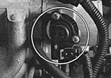
Absolute pressure sensor (MAP sensor)
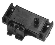
It is present both in cars with an injection engine and in HBO installations. Most often, it is installed in the engine compartment on the front shield. This sensor is required to determine the pressure change in the intake manifold depending on the current load and crankshaft speed. It comes with a 5V supply voltage. and takes data on the current pressure. The sensor is tight because the engine air system passes through it. Inside there is resistance with blades. Depending on the discharge, the blades bend, changing the resistance value. By changing the voltage at the output of the sensor, the computer understands how much air enters the engine and regulates the constant composition of the mixture. When the ignition is switched on, its 5V supply voltage should come at the extreme contacts. A signal is taken from the middle contact, the voltage of which at idle should be about 1.3 V.
Vehicle speed sensor

Screwed into gearbox. Functionally works as a Hall sensor. This sensor transmits pulsed signals to the electronic control unit (ECU), the frequency of which is directly proportional to the speed of rotation of the front wheels of the car. To check it, you need an oscilloscope. An ordinary tester cannot be checked. In the worst case, the speedometer will lie, or the speedometer will not show the speed of the car. This sensor does not affect the operation of the engine.
Oxygen concentration sensor (lambda probe)

The sensor on which the amount of fuel supplied to the engine depends. A sensor is installed in the exhaust manifold. Its task is to measure the amount of oxygen in the exhaust gas (exhaust). Using its values, the computer controls the state of the fuel-air mixture. If it malfunctions, fuel consumption increases, jerks appear, and exhaust toxicity indicators deteriorate. Its malfunction is determined during computer diagnostics of the car.
Today, with such a rapid development of technology, it is very important to know how to read car wiring diagrams. And do not think that it is only necessary for owners of modern foreign cars, which are full of automation. Even if you are old Lada, It will also be useful to get acquainted with this information, since the device of any machine requires the presence of auto electricians.
What are electrical circuits?
Wiring diagrams are an ordinary graphic image, which shows pictograms of different elements arranged in a certain order in a circuit and connected in series or parallel. Moreover, such drawings do not display the actual location of these elements, but only indicate their relationship with each other. Thus, a person who understands them, at a glance, can determine the principle of operation of the appliance.
Three groups of elements are always depicted in the circuits: power sources that generate current, devices responsible for converting energy, and nodes that transmit current; different conductors play their role. The power source can be galvanic cells with a very small internal resistance. And electric motors are often responsible for energy conversion. All the objects that make up the circuit have their own symbols.
Why understand electrical circuits?
Being able to read such schemes is quite important for everyone who has a car, because this will help to save a lot of money on the services of a specialist. Of course, it’s difficult to repair some serious damage on your own without the participation of professionals, and it’s fraught, because the current does not tolerate errors. However, if we are talking about any elementary malfunction, or if you need to connect, ECUs, headlights, side lights, etc., then doing it yourself is quite real.
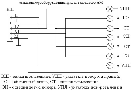
In addition, often we want to introduce additional electronic devices, such as alarms, radio, into the circuit, which greatly facilitate the process of driving and fill our life with comfort. And here you can not do without the ability to understand electrical circuits, because often they are attached to all of the listed devices. This is also true for owners of cars with a trailer, as sometimes there are problems with its connection. And then you will need an electric circuit of the trailer of a car and, of course, skills to understand it.

How to read car wiring diagrams - basic notation
In order to understand the principle of operation of a device, it will be enough for a knowledgeable person to look at the wiring diagram. Consider the main nuances that will help even a novice understand the chains. It is clear that not a single device will work without current supplied by internal conductors. These routes are indicated by thin lines, and their color must match the actual color of the wires.
If the wiring diagram consists of a large number of elements, then the track on it is represented by segments and gaps, while the places of their connection or connection must be indicated.
The numbers indicated on the nodes must correspond to real numbers. The numbers in the circles indicate the locations of the wire connections with a “minus”, and the designation of current-carrying tracks makes it easier to find elements located on different circuits. Combinations of numbers and letters correspond to detachable connections. There are special tables with which it is very easy to identify the elements of electrical circuits. They are very easy to find both on the Internet and in manuals for specialists. In general, auto-electric circuits are easy to read, the main thing is to understand the functionality of their elements and follow the numbers.
Each machine is equipped with electrical equipment, whether it is voltage consumers or its sources. All used devices, as well as the electrical circuits connecting them, are marked on the wiring diagram. How to independently decipher the conventions in electrical circuits, why is this necessary and what components does the equipment include? We will talk about this below.
What are automotive electrical circuits?
What devices and elements does the car wiring system and electrical equipment include? The principal wiring diagram is a visual image where all the pictograms of the components used are indicated without exception. All devices are in a specific order on the circuit, and with each other they can be connected both in series and in parallel. It should be borne in mind that the electrical circuit of a car or truck in fact does not show the actual location of the equipment. It only shows how all consumers and energy sources are connected.
![]()
Regardless of the machine, the circuit includes the following components:
- power system equipment used to generate voltage;
- devices used to convert energy;
- in addition, the network also includes components used to transmit current, i.e. conductors.
What opportunities open up to the car owner, versed in schemes?
In the auto circuit, every owner of the car should understand the electric circuit, because if there are malfunctions in the equipment, you can deal with the breakdown yourself. Naturally, if more complex problems occurred in the operation of the network and equipment, it is unlikely that it will be possible to identify them independently without experience. Especially when you consider that in modern cars more complex schemes are used, which is associated with the use of a larger number of various devices.
Also, the need to understand the operation of a particular scheme for a car may arise from those car owners who want to make adjustments to the system. For example, if you plan to make improvements and tuning a vehicle, this does not necessarily imply the use of upgraded body kits or bumpers. If the interior is tuned, the car owner can install a new audio system or Conder, in which case you can’t do without changes. In addition, you need to understand the operation of the circuit in case you decide to install an anti-theft installation yourself.

Those motorists who periodically use the trailer should also be able to understand the scheme, since often our compatriots encounter a connection problem. One way or another, if you want to install additional devices and add their system, then understanding the wiring diagram is simply necessary.
How is the electrical equipment of any car?
As mentioned above, any on-board network includes energy sources, consumers, conductors, as well as control components. Energy sources include a car battery, as well as a generator unit. The purpose of the battery is to supply current to all consumers with the engine turned off, start it, and also when the power unit is operating at reduced speed. But the main source of energy is still considered to be a generator unit, which allows to supply power to all equipment and restore battery charge. It should be borne in mind that the battery capacity, as well as the power of the generator device, must fully comply with the technical parameters of voltage consumers, this is necessary to maintain the energy balance.
As for consumers, they are all divided into several groups:
- The main ones. These energy consumers include the fuel system, ignition, injection, engine control system (ECM), automatic transmission, and power steering, in particular the power steering.
- Additional. These include a cooling system, lighting and optics, active and passive safety, air conditioning, stove, car alarms, acoustics, as well as a navigation system.
- There are also short-term consumers. Such consumers include comfort systems, start-ups, horn, cigarette lighter (the author of the video is Kroom & coTV channel).
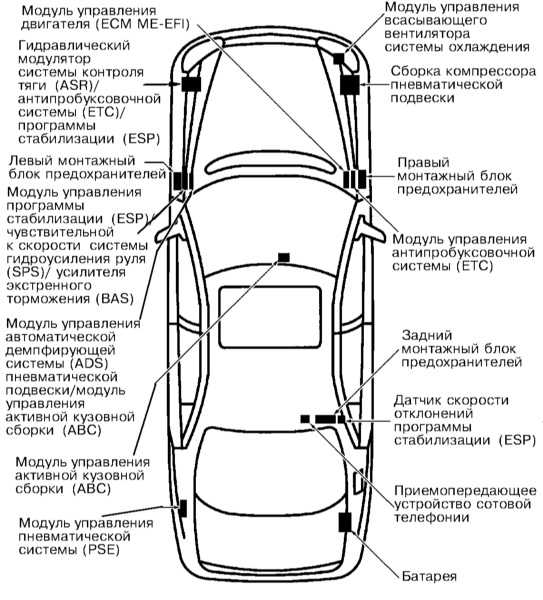
Also, any wiring system implies the use of control components. With their help, the coordinated work of energy sources, as well as its consumers, is ensured. The list of control components includes mounting blocks with safety devices and relays, control modules. These devices are usually located in a decentralized manner. In modern vehicles, most of the options that relays must perform are assigned to control modules, i.e. control units. Also, many cars today use multicomplex systems, in particular, data buses that connect electronic components.
The main aspects of the correct reading of the electrical circuit of the equipment
So, how to read car diagrams and what you need to know about their decoding? As you already understood, without knowledge of decryption, you will not be able to repair wiring and equipment if necessary. A detailed diagram for a specific car model should be noted in the service manual for the car. Looking at it, you can see dozens of various signs of electrical equipment, which are connected by lines. Each of these lines is painted in a specific color - this is the color of the wires in the wiring system (video shot by the MR.BORODA channel).
More modern cars use complex schemes, since such vehicles are equipped with a large number of equipment and devices. In such electrical circuits, conductors can be indicated by segments or with gaps.
What aspects for decoding the electrical circuit of a machine should be considered:
- As we have already reported, all electrical circuits are marked with a color corresponding to their actual state. This greatly facilitates the process of repairing and replacing wiring. The color of the conductors itself can be monophonic or double, this indicates whether this is the main cable or additional. In that case, if we mean additional conductors, then on the electrical circuit itself they are usually marked with dashed segments, which are either longitudinal or transverse.
- If in your car several electrical circuits are located on the same harness, while they are marked similarly, then such circuits are characterized by galvanic resistance. That is, these cables are simply interconnected.
- If the chain enters the harness, it will be marked with a slight deviation in a certain direction in which it is turned.
- Usually on any circuit there are several wires of the same color, usually black. In this case, we are talking about electrical circuits connected to ground, that is, the car body. Such contacts are called mass.
- Speaking directly about the relay, then in this case the contacts are indicated in the state when no energy is transmitted through the winding of the device. If the operating state of the device is standard, then these elements may differ from each other, since they can be open and closed.
- In addition, looking at the wiring diagram, you can see that additional symbols can be marked on the circuits themselves. Namely, we are talking about connecting an electrical circuit to an energy consumer. Such a designation will enable the consumer to find out exactly where the circuit is connected, while not accurately tracing its layout.
- If you notice that specific numbers are indicated on devices or equipment, then these numbers should correspond anyway. For example, if there is a circle around the number, this indicates that this is the point of connection of the circuit to the negative terminal. If you are interested in combinations of letters and numbers, then plug connections are marked.
Photogallery “Circuit Designations”


Conclusion
As a rule, along with the user's service manual, a special table is attached, with which you can optimally decrypt certain components of the power supply network. Those car owners who have never before encountered the need for decryption may have difficulty in performing this task. You need to be more careful to accurately decipher all the components and components. Directly, the decryption principle is similar regardless of what kind of car we are talking about - a foreign car or a domestic car.
Video "How to independently identify problems in the work of electricians?"
If you don’t know how to do it yourself to determine a malfunction in the car’s electrical wiring system, we recommend that you familiarize yourself with the video clip that describes this process in detail (video published by the High-frequency Auto electric channel).
Each car owner must know how to correctly decode the symbols that are present in the electrical circuits of a car. Indeed, in practice, a malfunction in the operation of electrical equipment can overtake the driver at any time, even on the road. Therefore, it is important to understand this issue in order to be able to eliminate the malfunction yourself if necessary.
What are electrical circuits?
In order to correctly read the basic decoding of automotive electrical circuits and know what the symbols mean in electrical circuits, we will first understand the concept. Schematic diagram of the electrical equipment of the car is a graphic image, on which pictograms of various components are shown. These components of the system device are installed in a certain order on the electrical circuit and they can be interconnected either in parallel or in series.
It should be noted that the electrical circuit of the car does not display the actual location of these components, but demonstrates their relationship with each other. That is, a car enthusiast who can figure out the system device with his own hands and read the decryption will understand the principle of electrical equipment at a glance.

Any vehicle electrical circuitry demonstrates several groups of components:
- power system devices designed to generate voltage;
- elements designed for energy conversion;
- as well as system devices necessary for voltage transmission (conductors perform this function).
Various galvanic components, characterized by a small internal resistance, act as power supplies for the system. All kinds of electric motors are designed to convert energy. In any case, the vehicle electrical circuitry contains objects conventionally marked on it.
Why understand electrical circuits?
Each owner of the vehicle should be able to read the basic wiring diagram for the designation of devices, since in case of a breakdown this will save money on repairs. Of course, without the participation of specialists, repairing more complex system malfunctions will be problematic. Moreover, the electrical equipment of a car, especially modern one, is a rather complicated system that will not tolerate errors. But if the electrical circuit breakdown is not particularly significant or you just need to connect the optics, then do it yourself is possible.
In addition, it is very important for those motorists who want to make changes to the operation of the system to understand what elements the electrical equipment of the car consists of. For example, today many domestic drivers make vehicle tuning with their own hands in various ways. This does not have to be the installation of new bumpers or body kits - sometimes you yourself want to do interior tuning yourself by installing a new multimedia system or air conditioning. In addition, Understanding the electrical circuit of a car with your own hands is also necessary if you are installing an anti-theft system - after all, you can’t do without a car’s protection at this time (author of the video is HF Auto Electric).
Also, it is necessary to read the wiring diagram for those drivers who have a trailer, since often there are difficulties in connecting it with your own hands to the system. In any case, if you decide to install additional equipment in the system, then the ability to read the electrical circuit is useful to you. At a minimum, without this, you will not be able to properly connect the wires with your own hands and configure the equipment.
How to read car wiring diagrams - basic notation
So, we will consider the main points that will allow you to correctly read the wiring diagram of the equipment of any vehicle. Indeed, as mentioned above, without this knowledge, it is simply impossible to repair devices with their own hands. Of course, no device can operate without voltage supplied to the device through internal conductors.
The wiring diagram of the vehicle with the designation of all elements must be in the service book for the car. Looking at it, you will take away a lot of different designations of devices and devices interconnected by lines. It should be noted that each of these lines can have its own specific color, which in fact should correspond to the actual color of the wires of the electrical circuit (the author of the video is High-frequency Auto Electric).
In the event that the car is equipped with multiple electrical appliances and devices, then a large number of components will be marked on the diagram. Accordingly, the wiring itself on it can be images of gaps and segments. At first, this can be confusing, but there is nothing complicated in this, it is quite possible to figure it out on your own.
Any circuit consists of the following elements:
- Power supply device. In this case, this function is performed by the battery or vehicle generator.
- Conductors, that is. These components allow the transmission of current through the network.
- Control equipment. Such devices are necessary to close the wiring or to open it if necessary. It should be noted that devices of this type may or may not be present on the wiring diagram.
- Directly consumers of voltage. This item includes all electrical equipment that consumes energy, converting current into another type of energy. For example, if it is a cigarette lighter, then this element converts the voltage into thermal energy.
If there is a need to repair the vehicle with your own hands, it is necessary to take into account the basic principles when deciphering the scheme:
- Any conductors, as mentioned above, are marked with a certain color in the diagram. As for the color itself, the wire can have one color or two, that is, it can be either primary or secondary. If we are talking about additional components, then strokes should be applied to them - they can be transverse or longitudinal.
- If several wires are installed on the same harness and are labeled the same, they have a galvanic connection. In other words, these conductors are simply connected to each other.
- In any circuit, if the conductor enters the harness, it should have a slight slope to the side where it is located.
- In practice, that is, on most circuits, conductors are marked in black that connect directly to the mass of the vehicle, that is, to its body.
- As for the relay, their contacts are marked in the state when voltage does not pass through the winding of the devices. In the standard state, these components are different because they can be either closed or open.
- You can also notice that certain signs can be located on the conductors, in particular, in the place where the wire is connected to the equipment. Thanks to this designation, the driver can immediately understand where this conductor is going, without tracing the circuit as a whole.
If certain mechanisms are indicated on certain mechanisms, then they must correspond to the numbers. If one or another number is marked in a circle, then this indicates that you have a conductor connection with a minus. As for digital and letter combinations, they correspond to detachable connections.
Included with the service book can be a table that allows you to easily decrypt certain network elements that are specific to a particular vehicle model. In general, if you have a need to decrypt the scheme, the most important thing is to be diligent in order to understand what this or that designation means. Having understood the principle of decryption, you can easily determine the purpose of all elements.
In foreign cars, other markings, but the principle is the same.
Video “Correctly deciphering circuit elements in a car”
More details about this issue are described in the video below (video author - MR. BORODA).
An electrical circuit is a specialized graphic image on which pictograms of various elements are shown that are in a certain order in a circuit, as well as connected in parallel or in series. At the same time, it is worth noting that any such drawing does not demonstrate the actual location of certain elements, but is used only to indicate their relationship with each other. Thus, a person who knows how to read electrical circuits, at a glance, can understand the principle of operation of a device.
There are three groups of elements in the circuit:
- power sources that take on the function of generating current;
- various devices that are responsible for further energy conversion;
- nodes transmitting current (conductors).
A variety of galvanic cells, characterized by a small resistance, can act as a source. In this case, various electronic motors are involved in energy conversion. Moreover, it is important to know the conventions of each individual object that make up this circuit, since it is difficult to read electrical circuits without this knowledge.
What are they needed for?
Many people often wonder why they are required at all. However, in reality, it is important for each motorist to understand them, because if you know how to read electrical circuits, you can subsequently save significantly on the services of professionals. Of course, it will not be easy for you to carry out independent repairs of any particularly complex malfunctions without involving qualified specialists in these works, and in principle, this is fraught with further complications. But if you need to fix some minor malfunction or connect the headlights, ECU, battery and other elements, you can even do it yourself if you know how to read electronic circuits.
Why are they for a motorist?
Often people want to introduce a wide variety of electronic devices into the circuit, including a radio, alarm, air conditioning and many other devices that greatly simplify the driving process and make our life more comfortable. In this case, it is also important to understand how to learn to read electrical circuits, because in the overwhelming majority of cases, they are necessarily applied to almost every device.
This is especially true for owners of cars with a trailer, because often there are a variety of problems with its connection. In such cases, it will be necessary to use the electric circuit of the trailer of a car, and at the same time be able to understand it, since learning to read electrical circuits in a short time will not work.
Basic concepts
To understand the principle by which a particular device works, a knowledgeable person can simply look at his electrical circuit. At the same time, it is quite important to consider several basic nuances that will help even a novice to read such drawings in detail.
Of course, no device can work properly without current flowing through the internal conductors. These paths are indicated by thin lines, the color of which is selected in accordance with the actual color of the wires.
In the event that a sufficiently large number of elements is included in the electrical circuit, the route on it is displayed in the form of gaps and segments, and the places of their connection or connection must be indicated without fail.
In addition, the numbers that are indicated on the nodes should also fully correspond to the real numbers, since it would be pointless to read electrical circuits (symbols) otherwise. The numbers indicated in the circles determine the places of connection of the "minus" with the wires, while the designation of current-carrying tracks makes it easier to find elements that are on different circuits. Combinations of letters and numbers are fully consistent with detachable connections, while there are a fairly large number of specialized tables with which you can simply identify the elements of any circuit. Such tables are easy enough to find not only on the Internet, but also in various manuals for specialists. In general, it is not so difficult to figure out how to read the circuit diagrams correctly. The main thing in this is to understand the functionality of various elements, as well as be able to properly monitor the numbers.
To understand how to read automotive electrical circuits correctly, you need not only to understand in detail the conventions of various components, but also have a good idea of \u200b\u200bhow they are formed into blocks. So that you can understand the features of the interaction between several elements of an electronic device, it is worth learning how to determine how the signal is transmitted and converted. Next, we will look at how to read electrical circuits. For beginners, the instruction is as follows:
- Initially, you need to familiarize yourself with the power circuit allocation scheme. In the predominant majority of cases, the places where the supply voltage is supplied to the cascades of the device are located closer to the top of the circuit. Power is directly supplied to the load, after which it passes to the anode of the electron lamp or directly to the collector circuit of the transistor. You should determine the place where the electrode is combined with the output of the load, since in this place the amplified signal is completely removed from the cascade.
- Install input circuits on each stage. You should select the main control element, and then study in detail the auxiliary that are adjacent to it.
- Find the capacitors located near the input of the cascade, as well as at its output. These elements are extremely important in the process of amplifying AC voltage. Capacitors are not designed to pass direct current through them, as a result of which the value of the input resistance of the next block will not be able to bring the cascade out of a stable state in direct current.
- Start exploring the cascades that are used to amplify a specific DC signal. All kinds of elements that form a voltage are combined among themselves without capacitors. In the vast majority of cases, such cascades operate in analog mode.
- The exact sequence of stages is determined in order to establish the direction of the signal. Particular attention in this case will need to be given to detectors, as well as all kinds of frequency converters. You should also determine which cascades are connected in parallel and which are connected in series. When using parallel cascading, several signals will be processed absolutely independently of each other.
- In addition to understanding how to read electrical, circuit diagrams, you should also understand the connection diagrams attached to them, which are commonly referred to as mounting. The layout features of the various components of the electronic device will help you understand which blocks in this system are the main ones. Among other things, the wiring diagram makes it easier to determine the central component of the system, as well as to understand how it interacts with auxiliary systems, since it is difficult to read automotive electrical circuits without these values.
How to learn?
Even if a person thoroughly understands the various conventions that are used in electronic circuits, this does not mean that he will immediately be able to understand how the signals are transmitted between the components. That is why, in order to learn not only to name specific components on the circuit, but also to determine their interaction with each other, it is necessary to master a certain number of techniques for how to read circuit diagrams.
Circuit types
First of all, you need to learn how to distinguish standard power circuits from signal ones. You should pay attention to the fact that the place where power is supplied to the cascade is almost always displayed at the top of the corresponding circuit element. The constant supply voltage in almost all cases initially passes through the load, and only with time is transmitted to the anode of the lamp or to the transistor collector. The connection point of a specific electrode with the lower terminal of the load will be the place where the amplified signal is removed from the cascade.
Input circuits
Often for those people who approximately understand how to read electrical circuits of a car, the input circuits of the cascade do not require any explanation. In this case, you should consider that the additional elements located around the control electrode of the active component are much more important than it might seem at first glance. It is with the help of these elements that the voltage of the so-called bias is formed, with which the component will be introduced into a much more optimal direct current mode. It should not be forgotten that the different active components have individual characteristics of the bias feed method.
Capacitors
Be sure to pay attention to the capacitors located both at the input and at the output of the cascade, which amplifies the alternating voltage. These capacitors do not carry out direct current, and therefore neither the input resistance nor the input signal have the ability to remove the cascade from the direct current mode.
Amplification cascades
Next, be sure to pay attention to the fact that certain cascades are used to amplify direct current. The design of such cascades completely lacks specialized voltage generators, while they are interconnected without the use of capacitors. Certain instances are able to work in analog mode, while some others work only in key mode. In the latter case, the minimum possible heating of the active component is ensured.
Sequence
If several cascades are used in the system at the same time, you will need to learn to understand exactly how the signal passes through them, since you cannot read the car’s electrical circuits correctly without this knowledge. It is necessary to develop skills in determining cascades that are engaged in certain transformations with respect to a signal, for example. It should be borne in mind that in one circuit several parallel cascade chains can be present simultaneously that process several signals absolutely independently of each other.
It is impossible to immediately outline all the subtleties, without the knowledge of which it would be possible to understand how to read electrical circuits correctly without any errors. It is for this reason that many people who do this professionally study specialized textbooks on circuitry.
How to draw?
Accordingly, before installing any electrical circuit, it is mandatory to draw an image of it, but it is worth noting that manufacturers do not always prefer to attach an electrical circuit to certain devices. If you are doing the assembly of electronic equipment with your own hands, you can complete this scheme completely independently. With the help of modern computer programs, this procedure has become extremely simple, and is conveniently performed even by beginners.

What is needed for this?
To carry out this procedure, you will need only a few available things:
- Paper.
- Standard pencil.
- A utility from Microsoft called Office Visio Professional.
Instruction manual
- Initially, you need to draw a schematic image of a specific device design on paper. The circuit performed in this way will provide the opportunity to correctly assemble the various elements of the system and arrange them in the correct sequence, as well as combine them with conditional lines that display the order of attachment of various electronic elements.
- For a more accurate numerical presentation of your electronic circuit, you need to use the above Visio program. After the software is fully installed, run it.
- Next you should go to the “File” menu and select “Create Document” there. On the presented toolbar, select items such as “Snap” and “Snap to grid”.
- Configure all page settings in detail. To do this, you need to use a special command from the File menu. In the window that appears, you will need to select the image format of the circuit and, depending on the format, already determine the orientation of the drawing. Best in this case would be to use landscape layout.
- Determine the unit of measure in which the electrical circuit will be drawn, as well as the required image scale. At the end, click OK.
- Go to the “Open” menu, and then go to the stencil library. You should transfer to the drawing sheet the necessary form of the main inscription, frame and a host of other additional elements. In the latter, you will need to make inscriptions that will explain the features of your scheme.
- To draw the components of the circuit, you can use already prepared stencils that are in the program library, or any of your own blanks.
- All kinds of blocks of the same type or circuit components will need to be depicted by copying the presented elements, making then the necessary additions and edits.

After the work on the scheme is completed, you should check how correctly it was composed. Also try to correct the explanatory labels in detail, and then save the file under the desired name. The finished drawing can be printed.