Earth mass balance Calculation of volumes of earthwork and compilation of a statement of volumes of work
3 CALCULATION OF VOLUMES OF EARTH WORKS AND COMPOSITION OF LIST OF VOLUMES OF WORKS
The vegetative soil layer is cut to a depth of hN \u003d 20 cm before excavation and poured in a separately provided place or taken outside the construction site. The cut-off area of \u200b\u200bthe plant layer (m2) is determined taking into account the possibility of further movement of machines and storage of materials by the expression:
Fr.s \u003d (LV + 20) * (BB + 20) \u003d (48.2 + 20) * (25.8 + 20) \u003d 68.2 * 45.8 \u003d 3123 m2
The volume of the cut soil layer (m3) is determined by the expression:
Vr.s \u003d Fr.S. * h.P.
Vr.s. \u003d 3123 * 20 \u003d 624.6 m3
The transportation distance of the cut vegetative soil layer with a bulldozer can be determined by the expression:
L1 \u003d (48.2 + 20) / 2 \u003d 34.1
The amount of soil in the exit trench is determined by the formula:
Vtr \u003d Htr2 (3b + 2mhtr (m "-m) / m") * (m "-m) / 6
Vtr \u003d 3.22 (3 * 4.5 + 2 * 0.5 * 3.2 (5-0.5) / 5) * (5-0.5) / 6 \u003d 125.79 m3
Where b is the width of the exit, with one-way traffic of dump trucks, b \u003d 4.5;
m "is the slope coefficient of the exit trench; for the bulldozer, m" \u003d 5
The estimated depth of the pit is determined by the formula:
hр \u003d hтр - hн
where hн - the value of the shortage of soil, taken equal to 15 cm
hr \u003d 3.2 - 0.15 \u003d 3.05 m
The amount of soil in the pit for the foundation of the building is determined by the formula:
Vk \u003d hp * (Bn * Ln + BB * LB + (Bn + BB) * (Ln + LB)) / 6
Where Lн and Вн - the length and width of the pit on the bottom, m;
LV and BB - the length and width of the pit on the top, m;
hр - the estimated depth of the pit (excluding the shortfall), m.
Vk \u003d 3.05 * (23.2 * 45.6 + 25.8 * 48.2 + (23.2 + 25.8) * (45.6 + 48.2)) / 6 \u003d 3506.32 m3
The volume of soil shortage in the pit is determined by the expression:
Vn \u003d Ln * Vn * hn
Vn \u003d 45.6 * 23.2 * 0.15 \u003d 158.688 m3
Planning area of \u200b\u200bthe bottom of the pit (m2):
Fpl \u003d Ln * Bn
Fl \u003d 45.6 * 23.2 \u003d 1057.92 m2
table 2
Volume statement earthworks
| Name of construction processes | Units measurements according to ENiR | Number of units measuring | Required machines and mechanisms |
| 1. Cutting of the plant soil of category I with a bulldozer | 1000 m2 | 3,123 | Bulldozer |
| 2. Transportation of a previously developed vegetative soil layer of category I by a bulldozer over a distance | 100 m3 | 6,24 | Bulldozer |
| 3. Development (loading) of the vegetative layer of soil of category I by an excavator with a direct shovel with a bucket capacity of 0.25 m3 with loading into a vehicle. | 100 m3 | 6,24 | Excavator straight shovel EO - 2621A, dump truck |
| 4. Development of soil of category I in the exit trench by an excavator with a backhoe with a bucket capacity Vkov \u003d 0.5 m3 with loading into a vehicle. | 100 m3 | 0,76 | Backhoe loader EO - 3322, dump truck |
| 5. Development of soil of category I in the excavation pit by an excavator with a backhoe with bucket capacity Vkov \u003d 0.5 m3 with loading into a vehicle. | 100 m3 | 28,165 | Backhoe loader EO - 3322, dump truck |
| 6. Development of soil shortfall of category II in the pit with a bulldozer with transportation to a distance of L2 \u003d 45, 6 m | 100 m3 | 1,58 | Bulldozer |
| 7. Development (loading) of previously developed category I soil with an excavator backhoe with bucket capacity Vkov \u003d 0,5 m3 with loading in the vehicle. | 100 m3 | 1,58 | Backhoe loader EO - 3322, dump truck |
| 8. The final layout of the bottom of the pit with a bulldozer | 100 m3 | 0,068 | Bulldozer |
4 SELECTION OF THE KIT OF MACHINES FOR THE DEVELOPMENT OF SOIL IN PITCHING
Earthworks should be as mechanized as possible. All main and auxiliary processes are carried out using machines and mechanisms.
In this section, it is necessary to choose a leading machine for excavating the soil in the pit, and auxiliary ones for transporting the soil, cutting the vegetation layer, etc.
4.1 SELECTION OF THE BULLDOZER
Cutting the vegetable layer and its transportation, finalizing the soil in the pit and planning the bottom of the pit is done with a bulldozer. The type of bulldozer is determined depending on the distance of soil transportation, which depends on the operation of the bulldozer when cutting the vegetation layer of the soil.
In each of the types of work performed, we determine the maximum distance of movement of the soil with a bulldozer. According to the guidelines p.17 on the basis of the maximum distance of movement of the soil we determine the type of bulldozer and its required traction force. According to table P 1.2. p. 32 of the methodological instruction on the basis of the required traction force we determine the brand of the bulldozer. For the selected brand of bulldozer table. P 1.2. p. 32, as well as ENiR collection 2 issue 1 §E2 - 1 - 22 p. 83 table 1 we write out the technical specifications.
Table 3
Technical characteristics of the bulldozer DZ-42
| Reference data |
|
| Bulldozer brand | DZ-42 |
| Base machine | DT-75 |
| Bollard pull, kN | 67,9 |
| Blade width, m | 2,56 |
| Cost Mash-h, rub | 205 |
| Costs for 1 hour of work, person-h / Mash-h | 1,1 |
| Type of blade | fixed |
This type of machine is used to develop a plant layer of soil with loading into a vehicle. According to the guidelines, table A1.3. p. 33 on the basis of the volume of the vegetative soil layer the capacity of the excavator bucket is determined by the direct shovel: the soil volume in the pit is 624.6 m3, then the excavator bucket capacity is 0.25 m3. Using ENiR collection 2 issue 1 §E2-1-8 table 5 based on the required capacity of the bucket of the excavator a direct shovel, we determine its brand - EO-2621A. For the selected brand of excavator, we use the training manual, table P 1.4. p. 33, as well as ENiR, collection 2, issue 1 §E2-1-8 we write out the technical characteristics of the excavator straight shovel.
Table 4
Specifications of the excavator direct shovel EO-2621A
| Name of reference data | Reference data |
| Excavator brand | EO-2621A |
| The largest radius of digging (R), m | 4,7 |
| Maximum digging height, m | 4,6 |
| 3,3 | |
| Digging radius at the parking level (Rst), m | 2,7 |
| Cost mash-h, rub | 253 |
| 1,65 | |
| Bucket capacity, m3 | 0,25 |
| Power, kWt, | 44 |
| Excavator Weight | 5,45 |
Backhoe excavator is used in the excavation of a trench with loading into a vehicle and in the excavation of a foundation pit with loading into a vehicle. Based on the total amount of soil in the pit and the entry trench to be developed by an excavator, a backhoe is shown in Table A.1.3. p.33 we determine the capacity of the excavator bucket; the backhoe is the sum of 3830 m3, which means the bucket has a volume of 0.5 m3. Using ENiR collection 2, issue 1 §E2-1-11 p.51, table 5, based on the required capacity of the excavator bucket, determine his brand is EO-3322.
For the selected brand of excavator using table A1.5. p. 34, as well as ENiR collection 2, issue 1 §E2-1-11, we write out its technical characteristics.
Table 5
Technical characteristics of the excavator backhoe EO-3322
| Name of reference data | Reference data |
| Excavator brand | EO-3322 |
| Bucket capacity, m3 | 0,5 |
| The largest digging radius R, m | 9,2 |
| The greatest digging depth, m | 5,6 |
| The highest unloading height, m | 1,7 |
| Cost Mash-h, rub | 325,2 |
| Labor costs for 1 hour of work, person-h / Mash-h | 1,65 |
4.4 SELECTION OF A CAR DUMP
For the removal of soil in technical works where excavators work, dump trucks are needed. Using the training manual, according to table P 1.7. p. 35 based on the capacity of the backhoe bucket, determine the brand of the dump truck - MAZ-5549. And according to table A.1.8. p. 36 for the selected brand of dump truck, write out its technical characteristics.
Table 6
Technical characteristics of the MAZ-5549 dump truck
| Name of reference data | Reference data |
| Mark | MAZ-5549 |
| Carrying capacity, t | 8,0 |
| Body capacity, m3 | 5,1 |
| Cost Mash-h, rub | 184,01 |
| Labor costs for 1 hour of work, person / hour / machine-hour | 1,79 |
5 CALCULATION OF LABOR COSTS
Table 7
| Name operations | Scope of work | Norm of time (Нвр), | Labor input, Mash-h, | ||||
| Qty | |||||||
| 1 | 2 | 3 | 4 | 5 | 6 | 7 | |
| Column a | 1. Cutting of the vegetative layer of soil of category I with a bulldozer DZ-42 | 1000 m2 | 3,123 | 0,84 | 2,62 | 6th category driver - 1 person | |
| Table 2, Column in, and | 2. Transportation of the previously developed plant soil layer of category I with a bulldozer DZ-42 at a distance of L1 \u003d 34.1 m | 100 m3 | 6,24 | 2,58 | 16,09 | Engineer of the 5th category - 1 person. | |
| Column a | 3. Development of the vegetative layer of soil of category I by an excavator with a direct shovel EO-2621A with a bucket capacity of 0.25 m3 with loading in a vehicle | 100 m3 | 6,24 | 3,5 | 21,84 | Engineer of the 5th category - 1 person. | |
| Column a | 4. Development of soil of category I in the exit trench by an excavator with a backhoe with a bucket capacity of 0.5 m3 with loading into a vehicle | 100 m3 | 0,76 | 2,8 | 2,12 | 6th category driver - 1 person | |
| Column a | 5. Development of soil of category I in the excavation pit by an excavator with a backhoe with a bucket capacity of 0.5 m3 with loading into a vehicle | 100 m3 | 28,165 | 2,8 | 78,86 | 6th category driver - 1 person | |
| Table 2, Column b, g | 6. Development of soil shortfall of category II in the pit with a bulldozer DZ-42 with transportation to a distance of L2 \u003d 45.6 m | 100 m3 | 1,58 | 4,44 | 7,01 | 5th category driver - 1 person | |
| Name operations | Scope of work | Norm of time (Нвр), | Labor input, Mash-h, | ||||
| Qty | |||||||
| Column a | 7. Development (loading) of previously developed soil of category I by an excavator with a backhoe with a bucket capacity of 0.5 m3 with loading into a vehicle | 100 m3 | 1,58 | 2,8 | 4,42 | 6th category driver - 1 person | |
| Table 2 row 1 Column b | 8. The final layout of the bottom of the pit with a bulldozer DZ-42 | 1000 m2 | 0,068 | 0,49 | 0,033 | 5th category driver - 1 person | |
| Total | 132,993 | ||||||
6 CALCULATION OF THE KIT OF DUMP CARS FOR TRANSPORTATION OF SOIL
The number of dump trucks is determined from the following expressions:
tc \u003d tp + 2L / vav + tp + tm
tp \u003d Nvr * Vka / (100Kpr) + tm
where tc - the duration of the cycle of the truck, h;
tp - truck loading time, h;
L is the distance of transportation of soil (table. 1);
Vav - the average speed of the truck, km / h (Table A.1.10);
tр - dump truck unloading time, accepted 0.017 h;
tm - the duration of the maneuvers of vehicles during unloading or installation for loading, accepted 0.017 h;
НВР - the norm of machine time for soil development by a leading excavator with loading into a vehicle, Mash-h;
Vka - the volume of the dump truck body, m3 (Table A.1.8);
KPR - the coefficient of initial loosening of the soil (table. P.1.11)
The resulting number of dump trucks is rounded to the nearest whole up.
tc \u003d 2.8 * 7.2 / (100 * 1.25) +0.017 \u003d 0.178
tc \u003d 0.178 + 2 * 4.4 / 15 + 0.017 + 0.017 \u003d 0.798
N \u003d 0.798 / 0.178 \u003d 4.483 ≈ 5
We accept the number of dump trucks MAZ-5549 in the amount of 5 pieces.
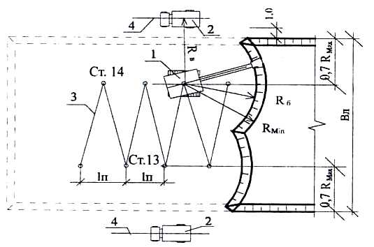
7 CALCULATION OF BOTTOM OF A SINGLE-BUCKED EXCAVATOR REVERSE SHOVEL
Backhoe excavator develops soil below the excavator's parking lot. Vehicles for the removal of soil from these excavators can be located both at the excavator's parking lot and at the bottom of the pit, however, the first scheme was most widely used.
There are several types of slaughter:
1) frontal face for an excavator straight shovel (end face for an excavator backhoe): straight ahead; zigzag movement; frontal (transverse-end)
2) side face
When calculating the bottom of an excavator, a backhoe needs to calculate the width of the end penetration movement in a straight line, along the zigzag and the width of the side penetration.
The width of the end (frontal) penetration in a straight line is determined by the expression:
VL (P) \u003d 2 (RV-0.5ba-1)
RB is taken by technical specifications
VL (P) \u003d 2 * (6.24-0.5 * 2.4 - 1) \u003d 8.08
RV \u003d 0.8 * 7.8 \u003d 6.24
The width of the end (frontal) penetration of the zigzag movement is determined by the formula:
VL (Z) \u003d Rp2 - ln2 + (RV-0.5 * ba-1)
Where Rр is the radius of soil cutting at the bottom of the pit, is taken according to the table. A.1.13. p. 38 method. directions.
Ln - the length of the working movement of the excavator, is taken according to the table. A.1.12. p. 37 method. instructions and depends on the type of equipment (direct / backhoe) and the capacity of the bucket.
VL (Z) \u003d + (6.24-0.5 * 2.4-1) \u003d 10.46
The width of the side penetration is determined by the formula:
WB \u003d (RV - 0.5 * ba-1) + -mhp
WB \u003d (6.24-0.5 * 2.4-1) + -0.5 * 3.05 \u003d 8.94
The result of calculating the section is to determine the soil development scheme in the pit. When determining the scheme, it is necessary to choose the type of the first end excavation of the backhoe and its width, as well as the number of side penetrations and the size of each of them so that the sum of the width of the first penetration and a certain number of side penetrations would clearly indicate the size of the excavation along the width of the upper part.
Determining the type of end penetration and the number of lateral:
1) Excavator end penetration, backhoe, straight ahead:
a) BB - VL (P) \u003d A1 \u003d 25.8-8.08 \u003d 17.72
b) A1 / WB \u003d B1 \u003d 17.72 / 8.94 \u003d 1.98
B1 - number of side penetrations
2) end excavator excavation backhoe, zigzag movement:
a) VV-VL (Z) \u003d A2 \u003d 25.8-10.46 \u003d 15.34
b) A2 / WB \u003d B2 \u003d 15.34 / 8.94 \u003d 1.71
B2 - the number of side penetrations
As a result of the calculation, we accept the following soil development scheme in the pit:
The first end penetration in a straight line, 8.08 m in size and two side penetrations, 8.86 m and 8.86 m wide.

End face of the excavator OL: 1- excavator; 2- dump truck; 3- axis of movement of the excavator; 4- axis of the movement of the dump truck.
Extended end face of the excavator OL: 1- excavator; 2- dump truck; 3- axis of movement of the excavator; 4- axis of the movement of the dump truck


Mobile painting station SO-188 with a productivity of 250 m 2 / hour. 2. TECHNOLOGICAL CARD FOR THE PRODUCTION OF CONCRETE WORKS WHEN ESTABLISHING A TYPICAL FLOOR. TECHNOLOGY AND ORGANIZATION OF THE PROCESS For the construction of walls, columns and ceilings, collapsible formwork is used. The technological process of formwork device is as follows: Formwork elements are installed manually or by crane ...
It was 4 points, then the total correction factor for this work in winter conditions, taking into account the wind force, will be 1.6 + 1.6 · 0.15 · 5/25 \u003d 1.648. 3) In the production of construction, installation and repair-construction works carried out in winter conditions in the open air and in unheated rooms, the norms of time and price should be multiplied by the average coefficients presented in the UniR (table ...
XXIII 0.11 -0.14 0.25 100 44.00 56.00 XXII-XXIII -0.10 0.11 0.21 100 47.62 52.38 XXIX-XXX -0.13 0.07 0, 20 100 65.00 35.00 XXX-XXXVII -0.07 0.07 0.14 100 50.00 50.00 XXXVII-XXXVIII -0.07 0.15 0.22 100 31.82 68.18 2.8 Definition earthwork volumes elementary site numbers working marks, m² / 4 Volume of figures h1 h2 h3 h4 ...
Almost on every projected section of the park, square, boulevard, etc. it is necessary to carry out excavation work, both in excavating and arranging embankments, or to make a site plan with the movement of the removed soil to a lower part of the site. Comparison of the volumes of earth masses of the recesses with the volume of embankments gives a balance of earth masses. Balance called active when the volume of excavations is greater than the volume of embankments and excess soil is transported to useless dumps (cavaliers), and passivewhen the volume of soil from the recesses is not enough for the device of embankments and useless excavations are made to fill the deficiency.
The best solution to the issue of placing earth masses on a construction site is the case zero balancein which the volume of soil from the useful excavations is fully utilized and is sufficient for the construction of useful embankments.
To obtain equal volumes of excavations and embankments, it is necessary to determine the mark of the layout of the area at which a zero balance of earth masses will be obtained.
The work is carried out in the following order:
1. The construction site, which should be planned with the condition of obtaining a zero balance of earth masses, is divided into squares with sides butequal from 10 to 50 m (figure 2.1 but).
2. At the vertices of each square, the geodetic mark is calculated H terrain by interpolation along the line of the largest slope between the horizontals.
Figure 2.1 Breakdown of the terrain into squares when determining the average (planning) elevation mark
3. Determine the average elevation of the surface of the site by the formula
![]() , m (2.1)
, m (2.1)
where and is the sum of the black marks of the vertices common for four and two squares, respectively;
- the sum of the marks of the vertices belonging to one square;
n is the number of squares.
4. Mark H cf conditionally taken as zero and working marks are determined in relation to it hexcavations and embankments that are discharged at the tops of squares (triangles). It is customary to indicate the working elevation marks of the embankment with a positive sign (+), and the depth marks of the excavation with a negative sign (-).
5. A line is plotted on the terrain plan zero work with the determination of its position by the formula
where x - the desired distance between the points of location of the zero line and the point of the working elevation;
h 1 h 2 - working marks, respectively embankments and excavations;
but - the width of the square.
6. As a result of the line of zero work on the grid of squares, geometric shapes are revealed - “square”, “trapezoid” and “triangle”.
Calculate the area of \u200b\u200bgeometric shapes and find the average working elevation in each figure.
The area of \u200b\u200bthe figure is multiplied by the average working elevation and thus the amount of earthwork in this figure is obtained.
If the square does not intersect with the zero line, then all four working marks of its vertices have the same sign and within it there will be only a notch or only a mound. An array of soil in such a square is a tetrahedral prism, the volume of which is equal to
![]() (2.3)
(2.3)
where a is the length of the side of the square, m;
h 1, h 2, h 3, h 4 - working elevations of its vertices, m
The volume of soil in the square intersected by the zero line will consist of a excavation and embankment. In this case, there are two types of such transitional (mixed) squares:
Squares dissected by the zero line into two trapeziums (Figure 2.2 but);
Squares dissected by the zero line into a triangle and a pentagon (Figure 2.2 b).

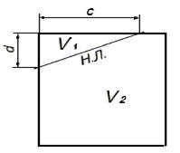
Figure 2.2 Types of transition squares dissected by a zero line on:
a) two trapezoid; b) a triangle and a pentagon
For the first type of transition square, the lengths of the segments of the sides intersected by the zero line:
Hence d \u003d a - c; (2.4)
Hence f \u003d a - e. (2.5)
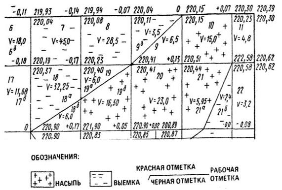
Figure 2.3. An example of a drawing of a cartogram of earthworks at a site
green area
This section calculates the total amount of soil processed during the construction process, summarizes its movement, cutting and refilling. In this calculation, it is necessary to take into account the soil processed in the vertical layout of the territory, soil displaced by the installation of coatings for paths and sites, as well as when replacing the soil with fertile soil in landscaping areas, fertile soil.
The soil moved during the vertical layout of the territory is calculated in subsection 1.6 of table 1.1. The volumes of soil displaced when arranging paths and sites were calculated in subsection 2.2 of table 2.4, and the soil displaced when replacing fertile soil in landscaping areas in subsection 2.1 of table 2.3. The amount of excavated soil due to loosening will exceed the calculated amount by the value of the loosening coefficient. The coefficient of loosening, we take equal to 10%. Consequently, the total amount of displaced soil will increase by 10%.
Fertile soil is soil that is previously cut in areas of vertical planning, as well as in areas of construction of various structures that are not subjected to vertical planning. The total volume of fertile soil is calculated based on the area on which the vertical layout is carried out, the area of \u200b\u200bpaths and sites, designed buildings and structures in areas that are not exposed to the vertical layout, and the thickness of the fertile layer. In our case, the volume of fertile (V pl ) we do not expect soil, since preliminary cutting of fertile soil is not provided for (IV soil category).
The amount of fertile soil used for landscaping the area is the amount of fertile soil needed to arrange the lawn, flower beds, as well as the amount of fertile soil introduced into the pits when planting trees and shrubs. The total amount of soil required for landscaping is calculated in subsection 3.1 (table 3.3).
The results of the calculation of work with various types of soils are given in table 4.1.
Table 4.1 - Statement of volumes of earth masses
|
Name of soil |
Quantity, m 3 |
|
|
Mound (+) |
Notch (-) |
|
|
1. Ground layout | ||
|
2. Displaced soil | ||
|
Including: | ||
|
a) when paving | ||
|
b) when replacing soil with fertile soil in landscaping areas | ||
|
3. Compensation correction (residual loosening) | ||
|
Total suitable soil | ||
|
4. Lack of suitable soil | ||
|
5. Fertile soil, total | ||
|
Including: | ||
|
a) used for landscaping | ||
|
b) lack of fertile soil | ||
|
6. Total processed soil | ||
From this statement it is clear that when working with the ground (when carrying out vertical planning of the territory, when arranging paths and platforms, when planting greenery), 7477 m 3 of soil is displaced (taking into account the compaction correction). As a result, there is an excess of suitable soil. There is not enough fertile soil: 379 m 3 is required. Transportation of 379 m 3 of fertile soil to the developed territory is required.
Continuation of table 5.1
|
7. Rolling soil in two sets of rollers |
MTZ-320 Skating rink of KVG-1,4 | |||||||
|
8. Sowing herbs with a seeder |
MTZ-320 Seeder "Egedal" mod. 83 |
bluegrass meadow, kg | ||||||
|
red fescue, kg | ||||||||
|
9. Sowing the lawn manually in places inconvenient for passage mechanisms | ||||||||
|
pasture ryegrass, kg | ||||||||
|
11. Watering the lawn with a watering machine |
5.1.1 Loosening the lawn base. Lawn construction begins with loosening the base to a depth of 20 cm, depending on conditions. Thanks to this operation, the base acquires a porous structure, which ensures good water and air exchange.
5.1.2 Land leveling. The operation is carried out with the aim of creating a flat surface without lowering and raising. Leveling is carried out mechanically and manually on inaccessible to mechanisms sections of the lawn. In this case, a rake is used, stones, weed roots, and garbage are carefully selected from the top layer. The amount of plant land is determined by the thickness of the root layer, which is taken 15 cm, therefore, 100 m 2 requires 15 m 3 of plant land.
5.1.3 Manually spreading plant soil. This operation is carried out by throwing the earth in those places where mechanisms do not pass. Manual work in places is planned on 10% of the area.
5.1.4 Application of mineral fertilizers. The application of mineral fertilizers contributes to a better and faster germination of seeds. The types of fertilizers used are shown in table 5.2.
Table 5.2 - Mineral fertilizers
5.1.5 Harrowing the soil in two passes. After applying fertilizers and leveling the plant soil, harrowing is carried out with a ZBS-1 harrow based on MTZ-82 to plant fertilizers to a depth of 3-5 cm and loosen the soil to obtain a finely lumpy structure.
5.1.6 Leveling the soil with a rake. Leveling is carried out with a selection of stones and roots in places that are inconvenient for the mechanisms and their approach on medium soils.
5.1.7 Rolling the soil with rollers. Soil rolling is performed by the KVG-1.4 skating rink on the basis of MTZ-320, which allows lowering the soil before sowing, as well as crushing the stones. Rolling is carried out in two passes with an ice rink.
5.1.8 Sowing seeds of lawn grass. Sowing of seeds is carried out by the Egedal mechanism based on MTZ-320, as well as manually. In this area of \u200b\u200bsoil, fertile fresh sandy loam; the place is well lit, so the following grass mixture was used: meadow bluegrass - 30%, red fescue - 50%, pasture ryegrass - 20%.